• Sign Up! To view all forums and unlock additional cool features

    Welcome to the #1 Dodge, Jeep and RAM Forum dedicated to FCA owners and enthusiasts. Register for an account, it's free and it's easy, so don't hesitate to join the SRT Forum today!


How-To: Cell Comm Killer.

OP
Diboblo

Diboblo

5000 Posts Club
Founding Member
Wiki Contributor
Member ID
#1044
Messages
5,937
Reactions
29,663
Likes
352
City
Riverside
State
CA
Country
United States
Vehicle
2015 Dodge Charger Hellcat!
Thread Starter #41
Upon further inspection/thought:

How did you end up at the 10K ohm, 7W (fixed) wirewound resistor calculation?

Reason I ask, this will work fine for the purple (FAKRA D) connector, however, per my earlier comments in this thread, *IF* I need to also block the pink (FAKRA H) connector, I'm not sure if the resistance would be the same, and not sure how to calculate.

Obviously would need a different plug housing also.
The pink is FAKRA H.

In the FSM, under cell troubleshooting, they call out for a specific miller tool, to load the cell module, once the antenna is removed. Simply unplugging the antenna is NOT recommended, as it can cause damage to the mode.

The Miller tool has a load of 10k ohms. You could use a much smaller resistor, but it is difficult to add the faraday material to a 2 watt resistor.

I went with a WW resistor, because I wanted a 1%, close tolerance load. There is a small +/- window that HAL9000 is looking for. Anything outside that range and you will throw a code.


Last edited:
OP
Diboblo

Diboblo

5000 Posts Club
Founding Member
Wiki Contributor
Member ID
#1044
Messages
5,937
Reactions
29,663
Likes
352
City
Riverside
State
CA
Country
United States
Vehicle
2015 Dodge Charger Hellcat!
Thread Starter #42
I've uploaded several FSM's, with wiring suppiments, to the maintenance section. I think MY15-MY19.

Members reading this, please consider doing the same, for MY20-MY23. It would be a great help in moving forward with mods like this.


Member ID
#19817
Messages
36
Reactions
15
Likes
2
City
Mount Pleasant
State
SC
Country
United States
Vehicle
2023 Challenger
#43
I've uploaded several FSM's, with wiring suppiments, to the maintenance section. I think MY15-MY19.

Members reading this, please consider doing the same, for MY20-MY23. It would be a great help in moving forward with mods like this.
Would be a huge help.

TY for uploads already there.


Member ID
#19817
Messages
36
Reactions
15
Likes
2
City
Mount Pleasant
State
SC
Country
United States
Vehicle
2023 Challenger
#44
The pink is FAKRA H.

In the FSM, under cell troubleshooting, they call out for a specific miller tool, to load the cell module, once the antenna is removed. Simply unplugging the antenna is NOT recommended, as it can cause damage to the mode.

The Miller tool has a load of 10k ohms. You could use a much smaller resistor, but it is difficult to add the faraday material to a 2 watt resistor.

I went with a WW resistor, because I wanted a 1%, close tolerance load. There is a small +/- window that HAL9000 is looking for. Anything outside that range and you will throw a code.
This may be a silly question, but in your design, how do you keep the Faraday cloth (conductive) from shorting the resistor leads? Do you shrink the connector/resistor combo first, and then wrap with Faraday, then do a second heatshrink over the faraday wrap?

Or maybe coat the center lead in epoxy all the way to the resistor housing?


OP
Diboblo

Diboblo

5000 Posts Club
Founding Member
Wiki Contributor
Member ID
#1044
Messages
5,937
Reactions
29,663
Likes
352
City
Riverside
State
CA
Country
United States
Vehicle
2015 Dodge Charger Hellcat!
Thread Starter #45
This may be a silly question, but in your design, how do you keep the Faraday cloth (conductive) from shorting the resistor leads? Do you shrink the connector/resistor combo first, and then wrap with Faraday, then do a second heatshrink over the faraday wrap?

Or maybe coat the center lead in epoxy all the way to the resistor housing?
One lead, of the resistor, is soldered to the center contact of the connector. Once inserted into the connector body, I backfill the cavity with epoxy. This prevents signal shorting.

The other lead is left bare, bent over the resistor and soldered to the shield, of the connector. Since shield is ground (in this case), there is no need to worry about the faraday material dead shorting.

I think I covered the epoxy business, in the first post. Either way, that's the way I do it.


Member ID
#19817
Messages
36
Reactions
15
Likes
2
City
Mount Pleasant
State
SC
Country
United States
Vehicle
2023 Challenger
#46
Update:
Have crafted the blocker. Tested it with resistance meter, jacket-to-center-pin, reads ~10K as it should. No shorting. Faraday cloth has been wrapped several times around (5-10x thickness).

Installed said blocker on the FAKRA-d connector of the head unit, and oddly, I actually see an increase in 4G signal quality with the blocker installed, vs with the antenna completely disconnected.

Edit:
Closing in on the mystery. Reworking the blocker to test a theory as to why it's not seeming to function, will update once I figure it out.


Last edited:
Member ID
#19817
Messages
36
Reactions
15
Likes
2
City
Mount Pleasant
State
SC
Country
United States
Vehicle
2023 Challenger
#47
First, quick walkthrough of my process for crafting @Diboblo's blocker. This is needed to explain why mine was acting like an antenna at first:

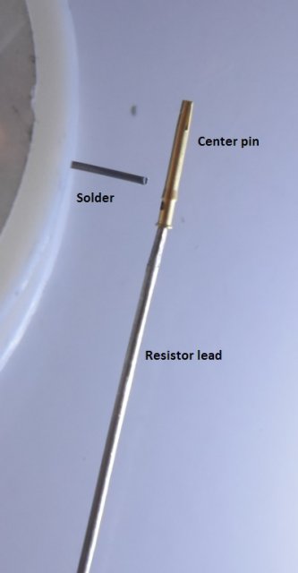
Found that sanding the resistor lead slightly and coating with flux allowed it to slip into the collar of the FAKRA connector's center pin. Solder can be done through the provided tiny hole in the pin if the solder itself is small enough in diameter.

0.jpg

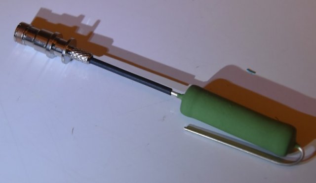
Thin heatshrink used to protect the resistor lead.
1.jpg

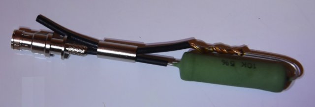
Required a small piece of wire to reach from the resistor lead back to the casing. Wrapped/soldered this in place.
2.jpg

Attached other end of wire to plug housing. I also added a full heatshrink wrap of this assembly when finished [NOTE: had to remove this heatshrink later, explanation below.]
3.jpg

Faraday cloth wrap around interior heatshrink:
4.jpg

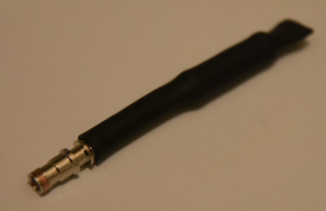
Finally, another heatshrink tube around the whole faraday cloth wrapped assembly, then attached plug housing:
5.jpg


Assembly tested at 10K ohms resistance, as noted above. When attached, the 4G reception improved (compared to no antenna) instead of dropping.

I created a test using a handheld RF spectrum analyzer, which shows frequencies and signal strengths in real time. I found (to my surprise) that if I wrapped the plastic antenna in Faraday cloth, there was virtually no change at all in signals received by the analyzer. If I allowed the wrapped Faraday cloth to touch the brass base of the antenna, it instantly dropped almost all signals to near zero.

Using this information, I then disassembled the cell blocker and removed the inner heatshrink that I had put in. Then I wrapped the resistor/wire assembly directly in the Faraday cloth, and put one heatshrink around all of it (the way @Diboblo described in the original guide). This ensured the copper cloth contacts the plug housing, exactly as it did around the base of the antenna in my test.

Finally, I reattached the reworked device. For a short time (~20 minutes), the 4G reception dropped to zero (no signal)! Unfortunately, then the system regained 4G reception, even with the blocker installed.

Removed the blocker, tested resistance - no shorts, still measures correctly. Ideas/input welcome as to why this seemed to only work temporarily.


OP
Diboblo

Diboblo

5000 Posts Club
Founding Member
Wiki Contributor
Member ID
#1044
Messages
5,937
Reactions
29,663
Likes
352
City
Riverside
State
CA
Country
United States
Vehicle
2015 Dodge Charger Hellcat!
Thread Starter #48
First, quick walkthrough of my process for crafting @Diboblo's blocker. This is needed to explain why mine was acting like an antenna at first:

Found that sanding the resistor lead slightly and coating with flux allowed it to slip into the collar of the FAKRA connector's center pin. Solder can be done through the provided tiny hole in the pin if the solder itself is small enough in diameter.

View attachment 132888

Thin heatshrink used to protect the resistor lead.
View attachment 132889

Required a small piece of wire to reach from the resistor lead back to the casing. Wrapped/soldered this in place.
View attachment 132890

Attached other end of wire to plug housing. I also added a full heatshrink wrap of this assembly when finished [NOTE: had to remove this heatshrink later, explanation below.]
View attachment 132891

Faraday cloth wrap around interior heatshrink:
View attachment 132892

Finally, another heatshrink tube around the whole faraday cloth wrapped assembly, then attached plug housing:
View attachment 132893


Assembly tested at 10K ohms resistance, as noted above. When attached, the 4G reception improved (compared to no antenna) instead of dropping.

I created a test using a handheld RF spectrum analyzer, which shows frequencies and signal strengths in real time. I found (to my surprise) that if I wrapped the plastic antenna in Faraday cloth, there was virtually no change at all in signals received by the analyzer. If I allowed the wrapped Faraday cloth to touch the brass base of the antenna, it instantly dropped almost all signals to near zero.

Using this information, I then disassembled the cell blocker and removed the inner heatshrink that I had put in. Then I wrapped the resistor/wire assembly directly in the Faraday cloth, and put one heatshrink around all of it (the way @Diboblo described in the original guide). This ensured the copper cloth contacts the plug housing, exactly as it did around the base of the antenna in my test.

Finally, I reattached the reworked device. For a short time (~20 minutes), the 4G reception dropped to zero (no signal)! Unfortunately, then the system regained 4G reception, even with the blocker installed.

Removed the blocker, tested resistance - no shorts, still measures correctly. Ideas/input welcome as to why this seemed to only work temporarily.
Sorry for the delay in response. It's been a busy weekend...

I noted that I had some 1g bleed, for about a month, after I installed mine. After that, it seemed to give up the ghost and no signal, since then.

The pink connector is a Telematics color and is assigned by Dodge as Cell. Are you considering also blocking that one? My car only has the FAKRA D, so I can't quantify the FAKRA H connector contribution.


Lilschmied

Member
Founding Member
Member ID
#1052
Messages
54
Reactions
61
Likes
17
City
Nowhereville
State
Non-US
Country
United States
#49
Did you connect the blocker and unplug the 2nd antenna at the same time? Could be that the module switches antennas searching for the strongest link. Would be interesting to crack open one of the new units to see where those rf paths actually end up.


Member ID
#19817
Messages
36
Reactions
15
Likes
2
City
Mount Pleasant
State
SC
Country
United States
Vehicle
2023 Challenger
#50
Sorry for the delay in response. It's been a busy weekend...

I noted that I had some 1g bleed, for about a month, after I installed mine. After that, it seemed to give up the ghost and no signal, since then.

The pink connector is a Telematics color and is assigned by Dodge as Cell. Are you considering also blocking that one? My car only has the FAKRA D, so I can't quantify the FAKRA H connector contribution.
No worries, busy weekend here also.

I am planning to block pink as well, going to build a second blocker shortly for that one.

The integration manual for the Sierra aircard specifies the card supports 2 external antennas (primary and secondary) as well as a tertiary on-card integrated antenna, for a total of 3. Seems like perhaps a disconnected (open) state on the secondary antenna could be causing the air card to end up on its internal antenna. Worth a shot.

One further note for the observant - I ended up choosing a FAKRA-Z (water blue) connector to build from, as it's a neutral plug that will interface with both D and H.


Member ID
#19817
Messages
36
Reactions
15
Likes
2
City
Mount Pleasant
State
SC
Country
United States
Vehicle
2023 Challenger
#51
Did you connect the blocker and unplug the 2nd antenna at the same time? Could be that the module switches antennas searching for the strongest link. Would be interesting to crack open one of the new units to see where those rf paths actually end up.
Yes.

Started with both antennas unplugged. Connected blocker to primary antenna (purple): no change in signal. Connected secondary antenna (pink): signal strength improved. Disconnected pink antenna: 4G signal lost, stayed gone for multiple vehicle re-starts, and ~20 min of usage. Then 4G regained.

There may be a clue to that pattern, is why my next step is blocking pink.

As far as rf paths, I've got photos of the board traces.


MMissile

1000 Posts Club
Premium Account
Donating Member
HFCOTM
Member ID
#19101
Messages
1,977
Reactions
7,727
Likes
212
City
Macomb County
State
MI
Country
United States
Vehicle
2023 Challenger Hellcat WB
#52
This is intriguing stuff. I guess the silver lining, is that these cars are no longer produced. Once all the abilities of sending signals out are blocked.....should be good to go. I don't care about radio function at all.


Last edited:
Member ID
#19817
Messages
36
Reactions
15
Likes
2
City
Mount Pleasant
State
SC
Country
United States
Vehicle
2023 Challenger
#53
This is intriguing stuff. I guess the silver lining, is that these cars are no longer produced. Once all the abilities of sending signals out are blocked.....should be good to go. I don't care about radio function at all.
If you don't care about radio functionality, this process is WAY easier.

Open the head unit, disconnect the 3 small coax antenna wires, and the 1 ribbon cable that goes from the board to the AirCard. That powers off and disconnects the AirCard completely. Vehicle is no longer capable of TX/RX for cellular (3g/4g etc).

Wrap the ends in insulating tape (like Kapton) to avoid shorts, or remove the card entirely if you prefer. Close up the unit, done.

You'll lose all GPS satellite functionality as well. SiriusXM radio still works. If you dont't want SiriusXM (and any satcomm at all) just disconnect the blue/gold satcomm antenna from the back of the head unit. If you prefer, you can also use @Diboblo 's satcomm blocker.


OP
Diboblo

Diboblo

5000 Posts Club
Founding Member
Wiki Contributor
Member ID
#1044
Messages
5,937
Reactions
29,663
Likes
352
City
Riverside
State
CA
Country
United States
Vehicle
2015 Dodge Charger Hellcat!
Thread Starter #54
No worries, busy weekend here also.

I am planning to block pink as well, going to build a second blocker shortly for that one.

The integration manual for the Sierra aircard specifies the card supports 2 external antennas (primary and secondary) as well as a tertiary on-card integrated antenna, for a total of 3. Seems like perhaps a disconnected (open) state on the secondary antenna could be causing the air card to end up on its internal antenna. Worth a shot.

One further note for the observant - I ended up choosing a FAKRA-Z (water blue) connector to build from, as it's a neutral plug that will interface with both D and H.
Wow... they REALLY want to keep an eye on us. LOL.

Great info and much appreciated.


OP
Diboblo

Diboblo

5000 Posts Club
Founding Member
Wiki Contributor
Member ID
#1044
Messages
5,937
Reactions
29,663
Likes
352
City
Riverside
State
CA
Country
United States
Vehicle
2015 Dodge Charger Hellcat!
Thread Starter #55
Also, keep in mind, you can still have music via bluetooth even though you block sat and cellcomms. You can also.l have nav, via carplay, or androidauto.

For early builds, there are standalone carplay/androudauto modules that interface with the media hub, via usb. This way, you can still have nav, on screen.


Member ID
#19817
Messages
36
Reactions
15
Likes
2
City
Mount Pleasant
State
SC
Country
United States
Vehicle
2023 Challenger
#56
Two blockers completed and added to purple/pink antenna connections. Sadly, no drop in signal. This suggests to me that the card is simply ignoring the two external antennas and using the on-card embedded antenna.

I can test the resistance of the devices, but is there an easy way to test the shielding of the blockers while off the head unit, to confirm whether or not they are blocking RF effectively?


OP
Diboblo

Diboblo

5000 Posts Club
Founding Member
Wiki Contributor
Member ID
#1044
Messages
5,937
Reactions
29,663
Likes
352
City
Riverside
State
CA
Country
United States
Vehicle
2015 Dodge Charger Hellcat!
Thread Starter #57
Two blockers completed and added to purple/pink antenna connections. Sadly, no drop in signal. This suggests to me that the card is simply ignoring the two external antennas and using the on-card embedded antenna.

I can test the resistance of the devices, but is there an easy way to test the shielding of the blockers while off the head unit, to confirm whether or not they are blocking RF effectively?
My only thought is to make sure the faraday material is properly grounded to shield, by homing it out.

To test for RF, on the bench, you would have to generate a signal.


Member ID
#19817
Messages
36
Reactions
15
Likes
2
City
Mount Pleasant
State
SC
Country
United States
Vehicle
2023 Challenger
#58
My only thought is to make sure the faraday material is properly grounded to shield, by homing it out.

To test for RF, on the bench, you would have to generate a signal.
May need to come up with a way to attach the blockers as the "antenna" to my RF analyzer in place of the stock antenna. That way I could see a real-time frequency analysis and immediately tell if the shielding is working.

It would also be ideal to be able to shield or disable the onboard antenna on the aircard, to take that out of play.

Seems like cutting or shorting the traces for the antenna would be one way, shielding the card (insulated from the faraday cloth) would be another. Non-destructive is preferable. Any thoughts on best approach for this?


OP
Diboblo

Diboblo

5000 Posts Club
Founding Member
Wiki Contributor
Member ID
#1044
Messages
5,937
Reactions
29,663
Likes
352
City
Riverside
State
CA
Country
United States
Vehicle
2015 Dodge Charger Hellcat!
Thread Starter #59
May need to come up with a way to attach the blockers as the "antenna" to my RF analyzer in place of the stock antenna. That way I could see a real-time frequency analysis and immediately tell if the shielding is working.

It would also be ideal to be able to shield or disable the onboard antenna on the aircard, to take that out of play.

Seems like cutting or shorting the traces for the antenna would be one way, shielding the card (insulated from the faraday cloth) would be another. Non-destructive is preferable. Any thoughts on best approach for this?
I'd warp the onboard antenna portion, in faraday. 1st in maybe electrical tape, then in faraday.


Lilschmied

Member
Founding Member
Member ID
#1052
Messages
54
Reactions
61
Likes
17
City
Nowhereville
State
Non-US
Country
United States
#60
I read through the Sierra datasheet and don't see anything about an integrated antenna. I see 3 rf connections, gps and 2 cell. What documentation were you looking at? I'd like to take a gander at it as well.


Top